
The Wiring Mistake That Kills Monitors in MDVR Installations — And the Zero-Cost Fix
A monitor that dies three months after installation, with everything wired correctly and voltages that measured fine at commissioning, is one of the most frustrating failures in fleet electronics. It is also one of the most predictable — and the fix costs nothing but a cut wire.
Key takeaways
- Power the recorder from a permanent live and switch it with ACC, never the other way round.
- Ground the unit to the chassis, not to a convenient bracket.
- Keep video cable away from the alternator, ignition leads and inverter wiring.
- Test the whole loom before the panels go back on.
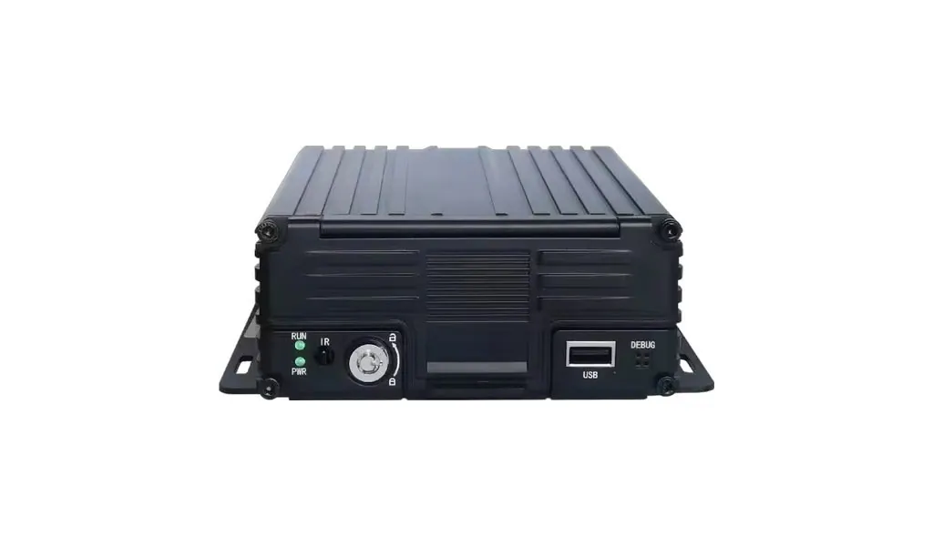
The failure pattern is consistent enough to recognise on description: a multi-channel installation with an MDVR and a monitor, both working perfectly on handover, followed by a monitor that will not power up some weeks or months later. The monitor is usually replaced under warranty. The replacement eventually fails too, which is the point at which the installation rather than the product becomes the suspect.
The shared cable is the problem
The standard 4-pin aviation cable that connects an MDVR to a monitor carries more than video. Depending on the pinout used, it can carry video, ground, a reverse trigger, and a +12 V conductor. On a typical arrangement:
| Pin | Function | Should be connected? |
|---|---|---|
| 1 | Video signal (AHD) | Yes — this is the reason for the cable |
| 2 | Ground | Yes |
| 3 | Reverse trigger | Yes, where the display switches on reverse |
| 4 | +12 V power from the MDVR | No — remove this conductor |
The critical failure is not the cable itself but what happens when that power conductor is present while the MDVR and the monitor are each powered from their own supply.
What actually damages the monitor
- Power feed between two separate supplies. The MDVR and the monitor draw from two different points in the vehicle electrical system, so their local ground references are not identical. A voltage difference of a few hundred millivolts between those two points is normal and harmless — until a conductor connects them directly. Current then flows along the least resistant path, which may run through the monitor’s power input and back through its internal rail. The monitor’s driver circuitry is not designed to accept current arriving from its output side.
- Start-up inrush from the recorder. An MDVR with a hard disk draws a substantial current transient when it starts: the disk motor spins up and the bulk capacitors charge. On a shared supply rail this appears as a dip followed by an overshoot. If the monitor is powered from the recorder’s own output, it sees that transient directly, every time the vehicle is started. A monitor designed around a 12 V nominal input can absorb a handful of such events. It cannot absorb them several times a day for a year.
- Ground loops. The monitor grounds at the dashboard, the recorder grounds at the chassis, and the video signal’s return path runs between them through the shield of the aviation cable. Any current flowing in that path — from a lamp, a wiper motor, a radio — is added to the video signal as interference, and simultaneously puts the two chassis points at slightly different potentials.
- Reverse polarity. A mis-pinned connector, or a cable re-terminated in the field, puts the vehicle’s positive feed onto the monitor’s ground pin. This is an immediate, non-recoverable failure on most monitors, and it is the single most common cause of a monitor that is dead on first power-up rather than months later.
- No fuse, or the wrong fuse, on the monitor feed. A monitor fed from a convenient live terminal without its own protection has no defence against any of the above, and no way for a fault to be isolated without taking the circuit down entirely.
The fix: remove the conductor, separate the feeds
The reliable solution is physical separation. Cut the +12 V conductor in the aviation cable — or order a cable manufactured without it — and give the monitor its own fused feed from the vehicle. Video, ground and the reverse trigger all remain intact, so operation is unchanged; the two devices simply no longer share an electrical path.
| Connection | Source | Protection | Purpose |
|---|---|---|---|
| MDVR power input | Vehicle battery through the ignition-switched fuse box | Per the manufacturer’s rating | Runs the recorder |
| Monitor DC input | Vehicle battery through the ACC circuit | Independent 2 A fuse | Runs the monitor, on its own circuit |
| Aviation cable pin 1 | MDVR video output | — | Carries the camera image to the monitor |
| Aviation cable pin 2 | MDVR ground | — | Signal return |
| Aviation cable pin 3 | Reverse lamp circuit | — | Switches the display on reverse |
| Aviation cable pin 4 | Not connected — conductor removed | — | Prevents any power path between the two devices |
The result is two devices on two independent fused circuits, with a single shared signal path that carries video and its return. There is no electrical route along which one can damage the other, whatever either of them does at start-up.
Why this shows up in heavy vehicles more than cars
Commercial vehicles are electrically more hostile, for three reasons that all push in the same direction:
- Longer ground paths. On a 12-metre vehicle and trailer, the physical distance between the dashboard ground point and the rear-mounted equipment is measured in metres of steel, which means measurable potential differences between them.
- Bigger loads switching on the same rail. Tail lifts, refrigeration units, work lights and hydraulic controls all draw and release large currents into the same harness. Every one of them produces a transient.
- Wider supply variation. Cranking a 12 V system can pull the rail down to single-digit volts momentarily, and 24 V systems in cold climates can dip well below their nominal value under load. Load-dump transients from an alternator running with a disconnected battery can exceed 100 V in an unprotected circuit.
This is why the voltage specification of the equipment matters as much as the wiring. A recorder rated for a DC 12–36 V input with reverse-polarity and transient protection is built for that environment; a monitor that stops working at 30 V is not, which is why the mirror-monitor family is rated for operation up to 40 V rather than the 30 V typical of generic units. When an alternator surges or a vehicle is jump-started, the difference between 30 V and 40 V is the difference between a working mirror and a blank screen.
Diagnosing a monitor that has already failed
- Check the fuse on the monitor feed first, and note its rating. A fuse that has been uprated because “it kept blowing” is evidence of a fault that was never found.
- Measure the voltage at the monitor connector while cranking, not with the engine off. A supply that measures 13.8 V at rest and 7 V during cranking explains a great deal.
- Check continuity between pin 4 on the cable and the vehicle positive. If the power conductor is present, the two devices are sharing a supply and the fault is understood.
- Measure between the monitor ground and the MDVR ground, with everything running. A reading above a few tens of millivolts indicates a ground path carrying current that should not be there.
- Inspect the connector for heat discolouration or a swollen housing. Overcurrent leaves a signature, and finding it confirms the diagnosis rather than replacing parts until the failure stops.
If you are specifying a multi-channel installation and want to avoid the problem by design, tell us you want isolated power for the monitor. We will supply the cable without the power conductor — a factory-modified CAB-01S aviation cable — and specify the independent fused feed as part of the wiring schedule, so the installation drawing and the delivered parts match.
This article covers the wiring around the recorder. For what to look for inside the recorder itself, see the MDVR buying guide, or the MDVR-708C as a worked example of an eight-channel unit.
Frequently asked questions
Why did my monitor work for three months and then fail?
Because the damage is cumulative. A shared power path between the recorder and the monitor exposes the monitor’s input to the recorder’s start-up transient every time the vehicle is started. Neither device is faulty; the wiring arrangement is. Isolating the monitor on its own fused feed removes the path.
Can I just put a diode or an isolator in the power line?
It can work, but it introduces a component that can itself fail, and a diode drops voltage that the monitor may not tolerate at the low end of the supply range. Removing one conductor achieves better isolation with nothing to fail. In hardware, the most reliable fix is often the one that deletes a connection rather than adding a part.
Does the video signal still work if I cut the power wire?
Yes. Video, ground and any reverse trigger remain connected, and the monitor still displays the recorder’s camera feed exactly as before. The only change is where the monitor gets its power — from the vehicle rather than from the recorder.
What fuse should the monitor have?
Typically 2 A on a 12 V monitor, selected to protect the cable and the monitor’s input rather than the device’s normal operating current. Never increase the rating to stop a fuse blowing: a fuse that blows repeatedly is reporting a fault, and the fault should be found rather than accommodated.
Related articles
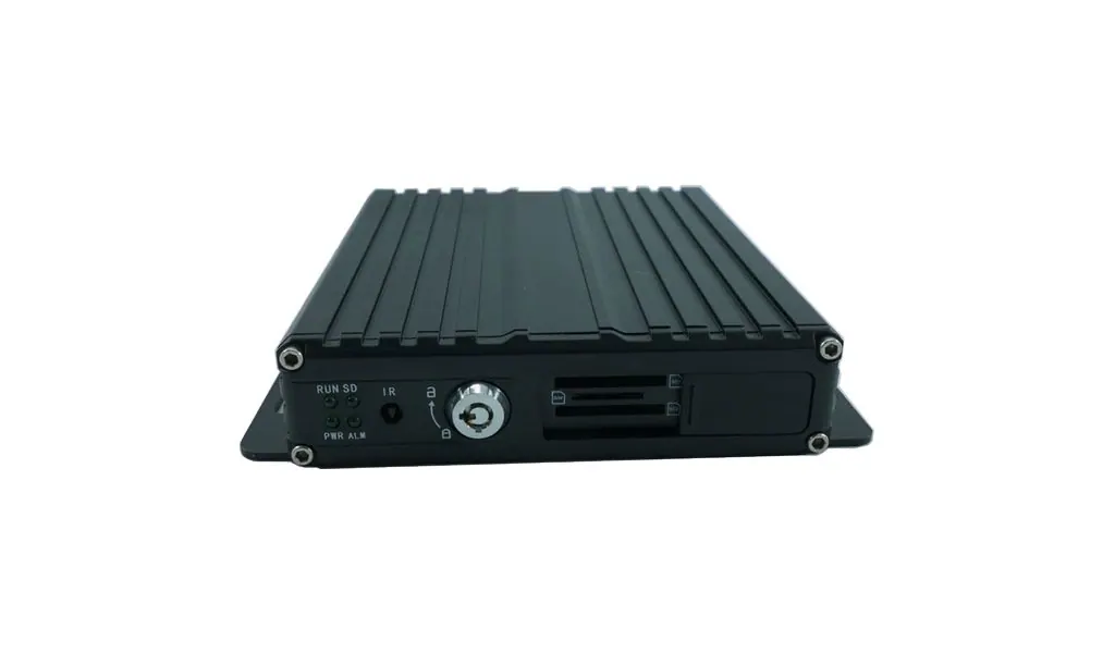
MDVR Buying Guide: How to Specify a Mobile DVR
How to choose a mobile DVR: channel count, SD versus hard drive, H.264 versus H.265, GPS and 4G, temperature ratings, UPS power and how much footage to keep.
Camera Latency by Interface: Why a Reversing Camera Must Never Be an IP Camera
Typical latency for LVDS, AHD, USB and IP video, how far a truck travels while the image arrives, and which interface suits each duty.
How to Choose a Truck Camera: The Complete Buyer's Guide
A practical guide to specifying commercial vehicle cameras: position, resolution, viewing angle, night vision, waterproof rating and connector type.
Looking for a reliable camera system supplier?
Tell us your vehicle type and application — we will recommend the right system and quote within 24 hours. Distributors and OEM/ODM projects welcome.